
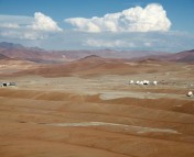
The other day, I had the special opportunity to visit the ALMA "Array Operations Site", on the Chajnantor plateau at 5000 meters elevation. Here we saw the current state of the array, which will soon incorporate half of its eventual 66 antennas (the array is expected to be complete in 2013)! This incredible sight got me thinking about how impressive it is that all of these distinct antennas function together as a single telescope, the largest astronomical project in the world. Back at the "Operations Support Facility" at 3000 meters, I took a walk around to see the antennas that are currently being assembled and tested, and I had a closer look at the process. More photos are included at the end of this post.
Note: This is the second astrobite in a periodic series chronicling my adventures doing astronomy research in Chile (click here to read the first astrobite of the series). For details on ALMA (the Atacama Large Millimeter/submillimeter Array), check out the observatory’s website, and go here for resources with more details on ALMA science and techniques.
An Introduction to Millimeter/Sub-millimeter Interferometry
An important feature of a telescope is its resolution, or the degree of detail that it can observe. The resolution depends on the ratio of wavelength of light to diameter of the telescope dish/mirror; in other words, observations will be higher resolution if they are of shorter wavelength light and/or made with a larger diameter telescope.
ALMA is sensitive to light with wavelengths that are from about 300 micrometers to 3 millimeters (approximately 0.0003 to 0.003 meters). This is called millimeter and submillimeter radiation, and it falls at the short wavelength (high frequency) end of the radio spectrum. For comparison, visible light has wavelengths about 1000 times shorter, between roughly 380 and 750 nanometers (0.00000038 to 0.00000075 meters). This balance of wavelength and telescope diameter results in the interesting fact that a single 7- or 12-m ALMA antenna “sees” only slightly more detail than your eye can see in visible wavelengths.
The science goals of ALMA require very high resolution. (A quick note: resolution is measured as an angle, and in this post I will use units of arcseconds. Remember, 1 degree equals 3600 arcseconds, and for reference, the apparent size of the moon is about 0.5 degrees, or 1800 arcseconds.) Given the wavelength constraints, the best way to achieve high resolution is to increase the size of the telescope. But, can you imagine making a telescope dish that is 16 km in diameter?
To get around this challenge, ALMA is actually an “array” of antennas that form a single telescope called an interferometer, and the antennas can be located in configurations spread up to 16 kilometers. The magic of interferometry allows two antennas placed a large distance apart to provide the same resolution as a single antenna having diameter equal to their separation; the more antennas, the better. The technique of interferometry combines the signals from all of the antennas using a supercomputer — the ALMA correlator. The entire ALMA array, with antennas arranged throughout the plateau, will be able to resolve details (at mm wavelengths) as much as ten times better than the Hubble Space Telescope (at visible wavelengths). ALMA will achieve an angular resolution of 0.004 arcseconds (the apparent size of a truck at the distance of the Moon).
In all, fifty 12-meter antennas will form the ALMA main array, with baselines (the distances between any two antennas) ranging from 15 meters to 16 km. Four more 12-meter antennas and twelve 7-meter antennas will form the Atacama Compact Array (ACA). The 7-m antennas can be clustered close together (without worry of collisions), and with these shorter baselines, they can detect larger, more diffuse structure within an observation. In addition, the 12-m antennas of the ACA are important for measuring absolute brightness of an object. This clever configuration accomplishes the best of interferometry and single-dish observations.
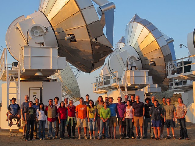
The ALMA Team
Making 66 antennas work together is a challenging feat, and it takes an international team to coordinate the efforts. ALMA is an international partnership between Europe, North America and East Asia in cooperation with the Republic of Chile. In the same way that all of the antennas must work together as one science machine, the partners also must work together as one observatory — the largest astronomical project in the world!
It was agreed that the partners are each responsible for delivering a portion of the antenna array. The European Southern Observatory (ESO) ordered its twenty-five 12-meter antennas from the AEM Consortium (Alcatel Alenia Space France, Alcatel Alenia Space Italy, European Industrial Engineering S.r.L., MT Aerospace). The North American partners have also provided twenty-five 12-meter antennas, ordered from Vertex RSI. The National Astronomical Observatory of Japan (NAOJ) ordered four 12-meter and twelve 7-meter antennas fom MELCO (Mitsubishi Electric Corporation).
Antenna Specifications
In order to ensure that the telescope functions as needed, the ALMA team decided on several specifications (well, more than several, in fact there are pages and pages of documents) for the antennas. Each company contracted to build antennas provided a prototype antenna to be extensively tested at the ALMA Test Facility in Socorro, NM. The array is considered “heterogeneous” because it is composed of antennas of four distinct designs.
A few of the (many) important specifications are:
- The surfaces must be accurate to 25 micrometers (in other words, more smooth than a thin sheet of paper, more thin than a human hair).
- The antennas must be able to point anywhere in the sky to an accuracy of 2 arcseconds and to track (continuously point to) an astronomical object to within 0.6 arcseconds (remember, 1 degree equals 3600 arcseconds).
- The antennas cannot exceed 105000 kg (100 tons!), and should try to minimize weight as much as possible.
- The antennas should be able to withstand the variable conditions of the site at 5000 meters elevation, with temperatures between -20 and 20 degrees C (-4 to 68 degrees F), and weather including wind, rain, snow, lightning.
- The antennas must have the proper interfaces for the antenna stations, so that each antenna can sit at any location within the array, and also be moved by the antenna transporter. The antennas must function with important components (i.e. receivers, calibration devices, electronics), which are the same in all antennas.
Four Antenna Types
The three types of 12-meter antennas have 3 distinct designs, and including the 7-meter antennas, ALMA includes four styles of antennas. Since all meet the specifications provided, there is clearly not one “correct” solution for designing the best antenna.
Here I list just a few of the novel methods which make these antennas some of the most advanced in the world. Several of these characteristics are shared among antennas of different types, but you can see in the photos that each antenna type is indeed distinct.
AEM 12-m — Much of the AEM antennas are assembled before delivery in Chile, and the antennas arrive in just a few main pieces (base, dish, and the yoke which connects the two). These antennas are driven by “direct drive” linear motors, in which permanent magnets propel the motion without any contact between the moving parts (no gears!). It’s a silent, peaceful method of movement. The linear motor segments are located outside the base, produce a large torque and can be easily accessed for maintenance.
Vertex 12-m — The Backup Structure (BUS, the part holding the dish) is made of Carbon Fibre Reinforced Plastic (CFRP), which is important because it is thermally stable against the harsh conditions at 5000 meter elevation. The BUS is joined to a steel cabin base structure by means of a large Invar support cone, ensuring that the thermal expansion of the steel cabin doesn’t affect the dish.
MELCO 12-m — These antennas have linear motors (no gears) with direct drive in two directions (azimuth and elevation, or side-to-side and up-and-down), to smoothly track a source during observations, and also switch between sources. Inside the base is a novel system to keep the cables from becoming wrapped up during observations as the telescope spins around to track a source.
MELCO 7-m — These antennas, although smaller than their neighbors, are nonetheless supported by sturdy conical bases equivalent to the bases that support the 12-m antennas. Hence, any antenna can attach to any antenna station, and this way many different configurations of antennas are possible.
A Walking Tour of the Antennas
A careful eye can distinguish each antenna type. Let’s take a look:

Notice the difference in quadrupods (the four-legged structures that support the secondary reflector at the top) in the AEM antenna on the left and the Vertex antenna on the right. Each antenna must have a quadrupod (with 4 legs), so that the images made by each antenna are compatible, but the exact design shape varies by antenna type.

The difference in quadrupods between the Vertex (left, nearer) and MELCO (right, farther) is more subtle, but you can see that the Vertex quadrupod legs extend to the edge of the dish, whereas the MELCO legs attach at the inner part of the dish.

The antennas have different base structures and drive mechanisms, for example the MELCO antenna on the left and the Vertex antenna on the right.

The 7-m antenna on the right appears to have an extra-bulky base, but it's actually the same size as the base of the 12-m antenna on the left. This way, any antenna can fit into any of the antenna stations. These MELCO antenna and AEM antenna have quadrupods that are similar, but not identical, with one larger than the other.

Here is the assembly and testing area for the MELCO antennas at the Operations Support Facility (3000 meters elevation). This 12-m antenna was brought down from the array by the special antenna transporter (the big yellow beast)** to undergo further testing. In the background, you can see a 12-m antenna on the ground awaiting its base structure, and several 7-m antennas (those with dishes not much wider than the bases).
** Note: There are two transporters, which are vehicles designed specially for this project. Each can operate at 3000-5000 meters elevation, travel up the 10 percent slope to the array, and with 28 wheels that each steer independently can place the 100 ton antennas with about 1 mm precision. Named Otto and Lore, these are two of the most important members of the ALMA team!
Disclaimer: The personal opinions and views expressed here are mine only, and do not necessarily represent those of ALMA or Fulbright.
I’d love to visit ALMA but it’s a little hard to convince people when you’re in Theoretical Astrophysics!
PS: You should really try using Hugin to stitch that panorama together. It’ll look really good and it is very easy to do.
http://hugin.sourceforge.net/
Hi Durand,
Well, we definitely need theoretical astrophysicists to keep up the hard work of explaining some of the physics behind what we observe. Hopefully one day there will be some opportunity to visit ALMA, and it would also be especially great for the public to learn more.
Thanks especially for the tip on Hugin — I have some more panoramas of the site I would love to stitch together.
Cheers,
Adele
Extremely impressive stuff. Thanks especially for taking photos and posting them.
Hi Mikhail,
I agree that ALMA is impressive, and I’m glad you enjoyed the post. I’m always trying to take photos of every aspect to convey the complex details of the project, and also the dramatic landscapes of Northern Chile. It’s my pleasure to share this experience with anyone who’s interested!
Cheers,
Adele